Archive
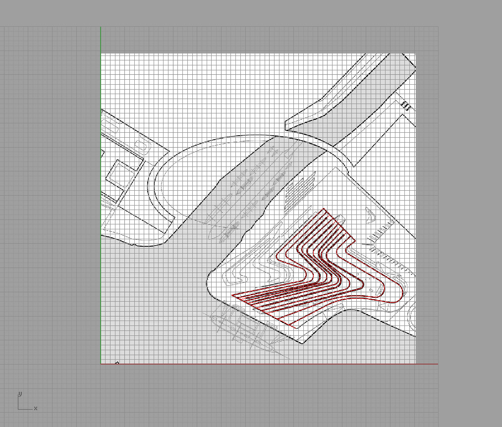
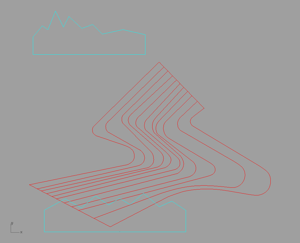
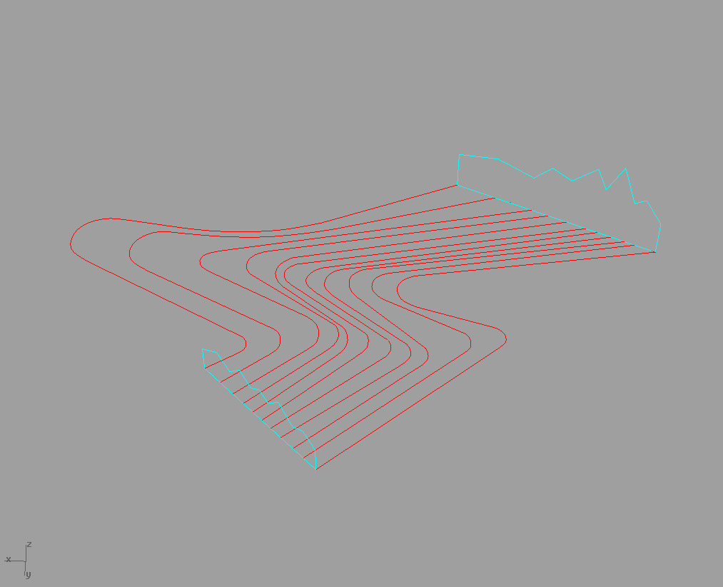
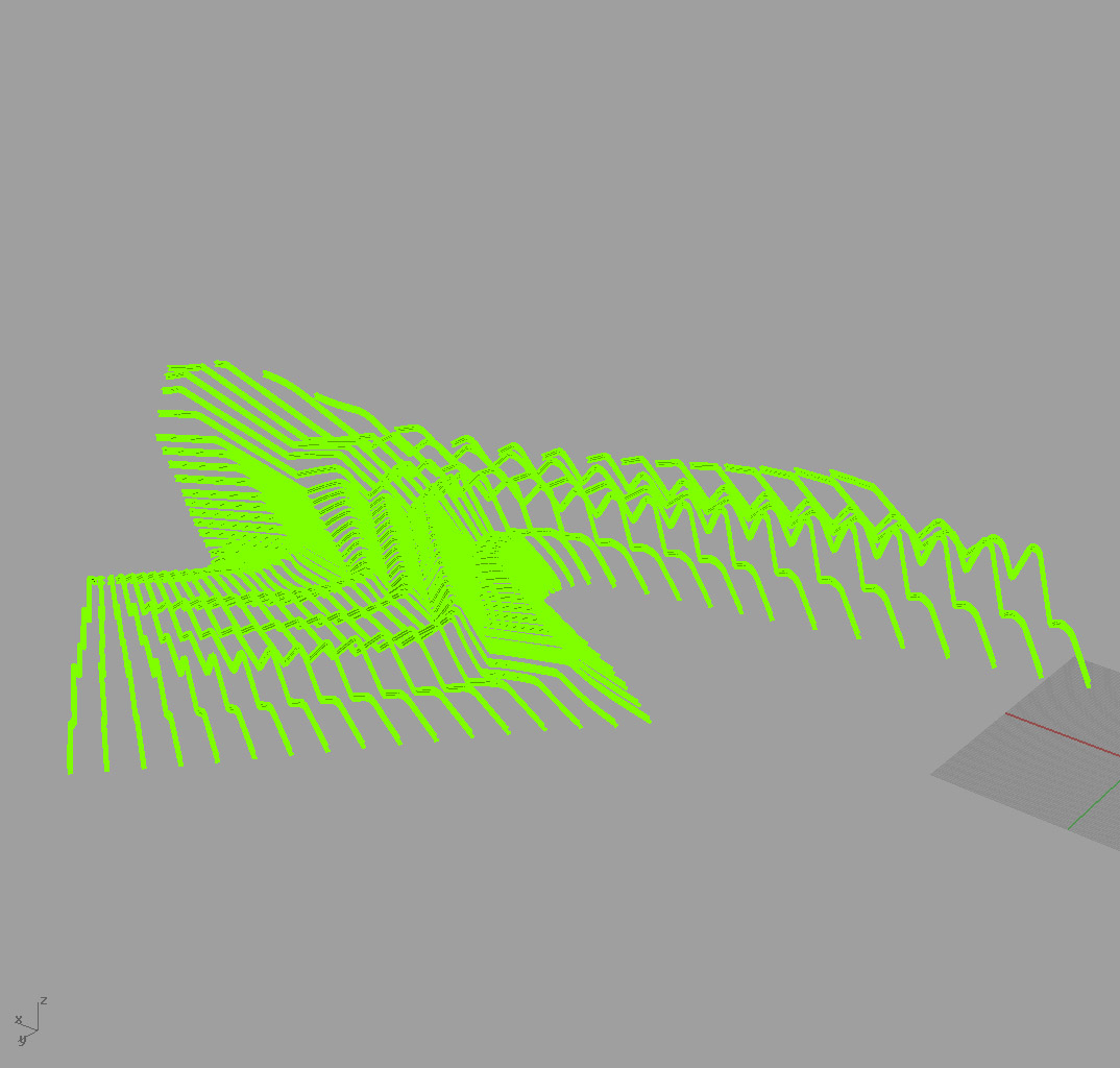
Rhino Lesson 3: Museum of Transport, Glasgow


Rhino Lesson 2: Eden Project

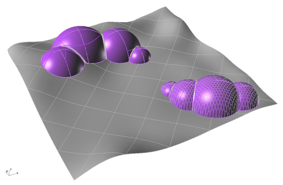


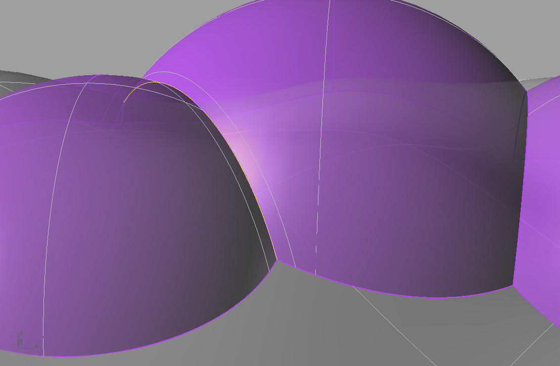


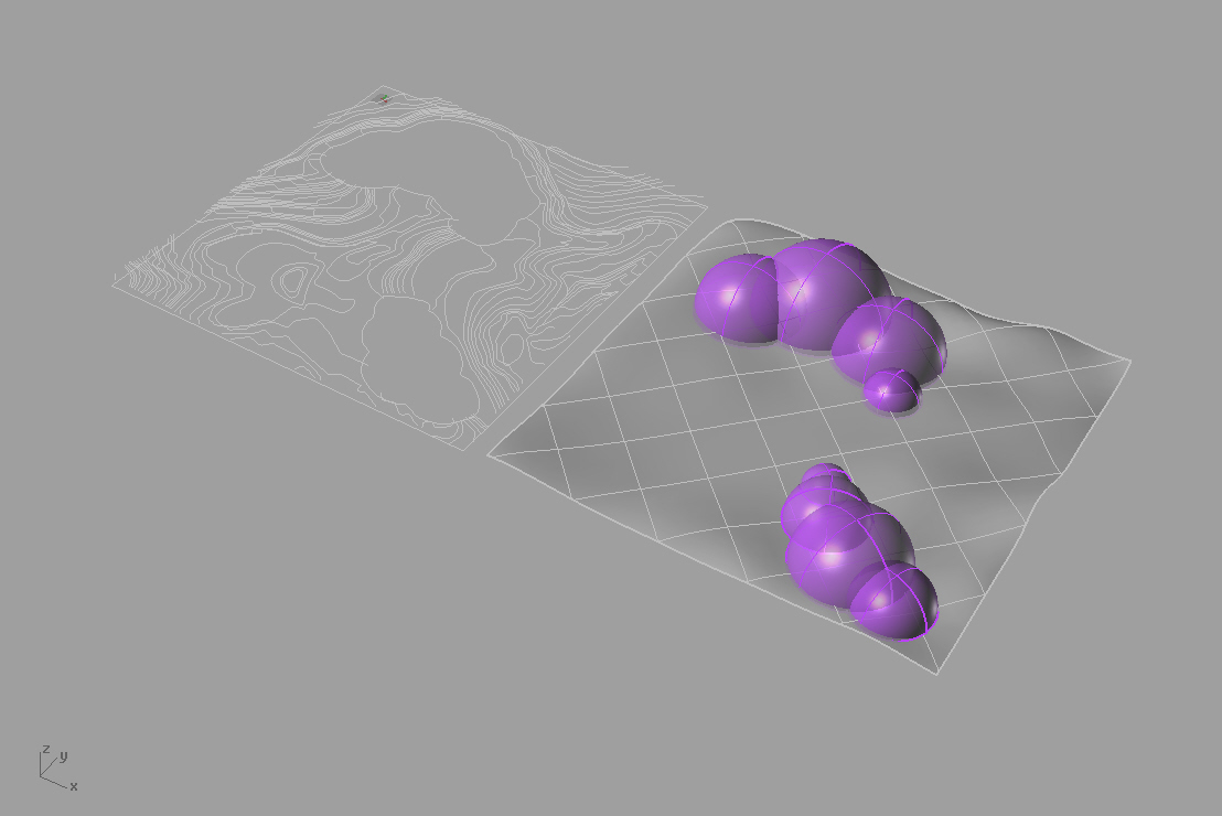
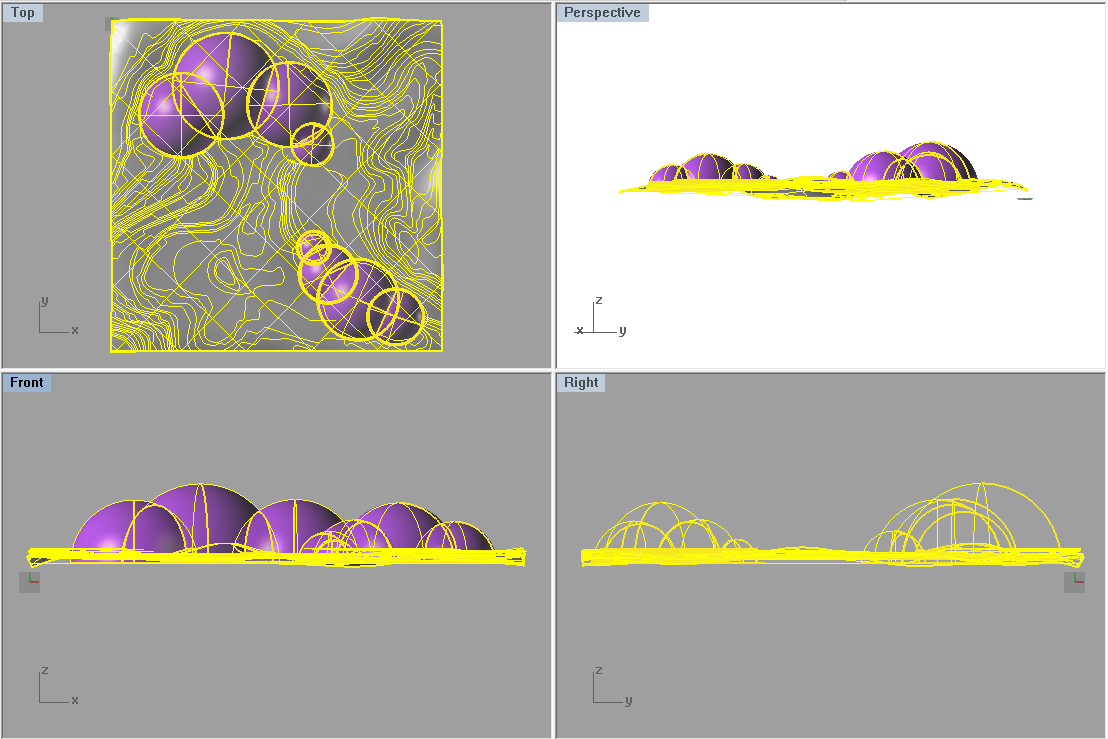


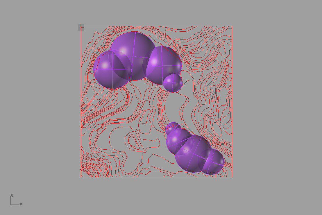
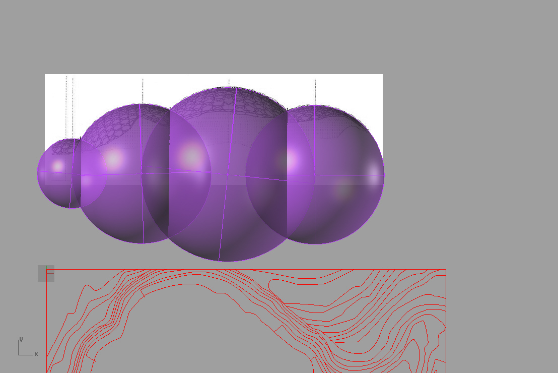


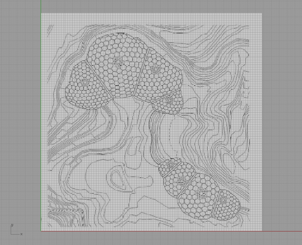
The Eden Project Rhino lesson begins with importing a site plan (Fig. 1). I began experimenting with drawing the spheres which would represent the geodesic domes (Fig. 2). Later I found that I would have to redraw them to an actual scale. The site has pronounded topography. I traced the topographic contours perhaps to too much exactitude which, in the end, was not so necessary with NURBs modeling it seems (Fig. 3). After scaling section of the Geodesic domes, I redrew the spheres to a more accurate proportion to the project (Fig. 4). The site was then scaled to match (Fig. 5). Fig. 6 illustrates how the spheres appear in elevation prior to trimming. Figs. 7 and 8 show the process of moving each contour to 1 foot intervals (in retrosepct, the spacing between should have been more pronounced. Fig. 9 demonstrates the patch command through all the contours and in Fig. 10 the geodesic domes are placed on the topography. The next step is to trim the spheres that fall below the site topography (Fig 11). Fig. 12 shows the topographic linework alongside the patched topographic surface. I did not find the site to be exaggerated enough to be true to the actual site conditions so I turn on the control points and, by eye, pulled or pushed the site to work (Fig.13). Figs. 14 and 15 show the process of triming the interiors of the overlapping spheres. I then offset each curve between the spheres to 10′ on each side of each geodestic dome (Fig. 16), trimmed between, and patched again to create the seams (Fig. 17.) Figure 18 is the completed site. I went a step further and tried experimenting with overlays of hexagonal shapes to mimic the geodestic domes. I arrayed the hexegons first (Fig. 19) and then projected the pattern onto the sphere surfaces (Fig. 20). Not so successful as the spheres shape does not allow for an even pattern distribution and in fact stretches the image on the surface.
