Archive
Urban SOS : Neblivela
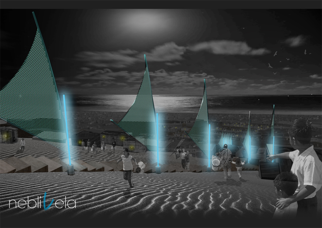
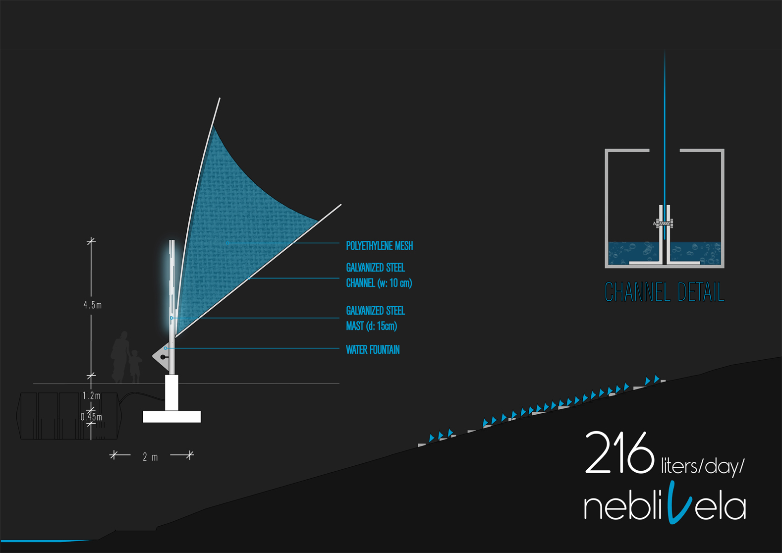
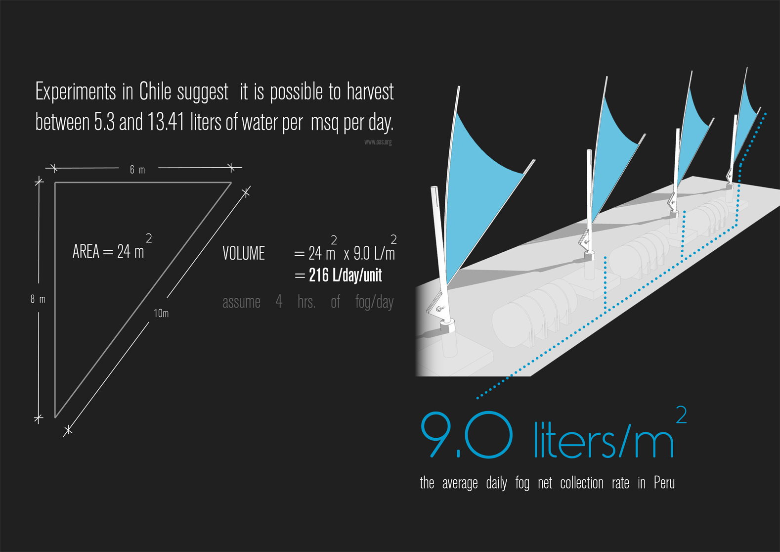
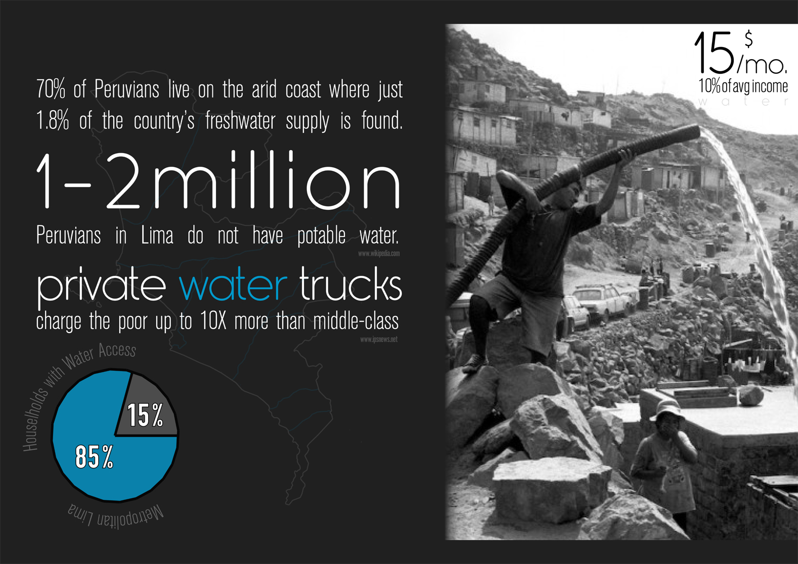
Peru is an incongruous land. Within hours, one leaves the scorching desert coastline, crosses the world’s highest tropical mountain range – the Andes – and descends into the planet’s largest tropical rainforest. Nearly 33% of the nation’s population resides in Lima, its sprawling capital city. Spread among 43 districts, informal settlements congest the burgeoning megacity. Uncontrolled urban growth often leaves the population without the services required for survival. Villa El Salvador is one such district, with origins as a shanty town. The village of Lomo de Corvina, a recent addition to the district, has rapidly overtaken the towering dunes bordering the Pacific coastline. Low precipitation along the arid coast, compounded by the irregular flow of nearby rivers, has created extreme water shortages, especially for the most vulnerable populations. 36% of Lima residents live below the national poverty level, and the economic inequality between rich and poor districts is evident in the distribution of water resources. However, the coastal environment conceals a natural means to support the inhabitants of this dry and inhospitable landscape. “Fog harvesting”, using “sails” upon metal structures can help mitigate the challenges of explosive population growth. An engineered fog “sail” will improve the lives of Lima’s poor by supplying free water, condensed from air. The NEBLIVELA system, which builds upon earlier methodologies of fog “capture”, is designed to integrate with the existing fabric of Villa El Salvador. NEBLIVELAs represent a positive, life-changing, system for the people who, until now, have been resigned to live with much less.


Rhino Lesson 1: Utzon Bagsvaerd Church
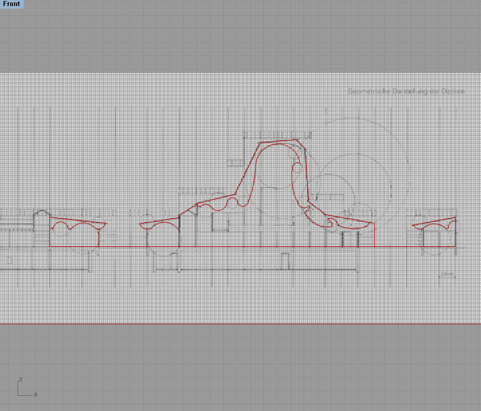
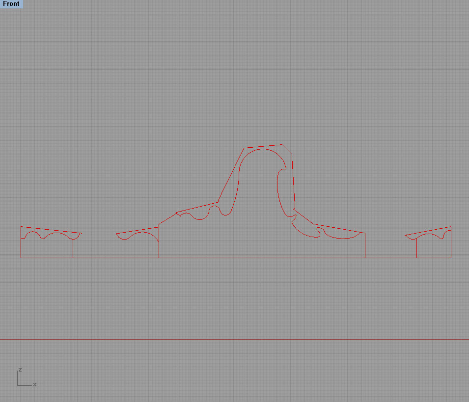
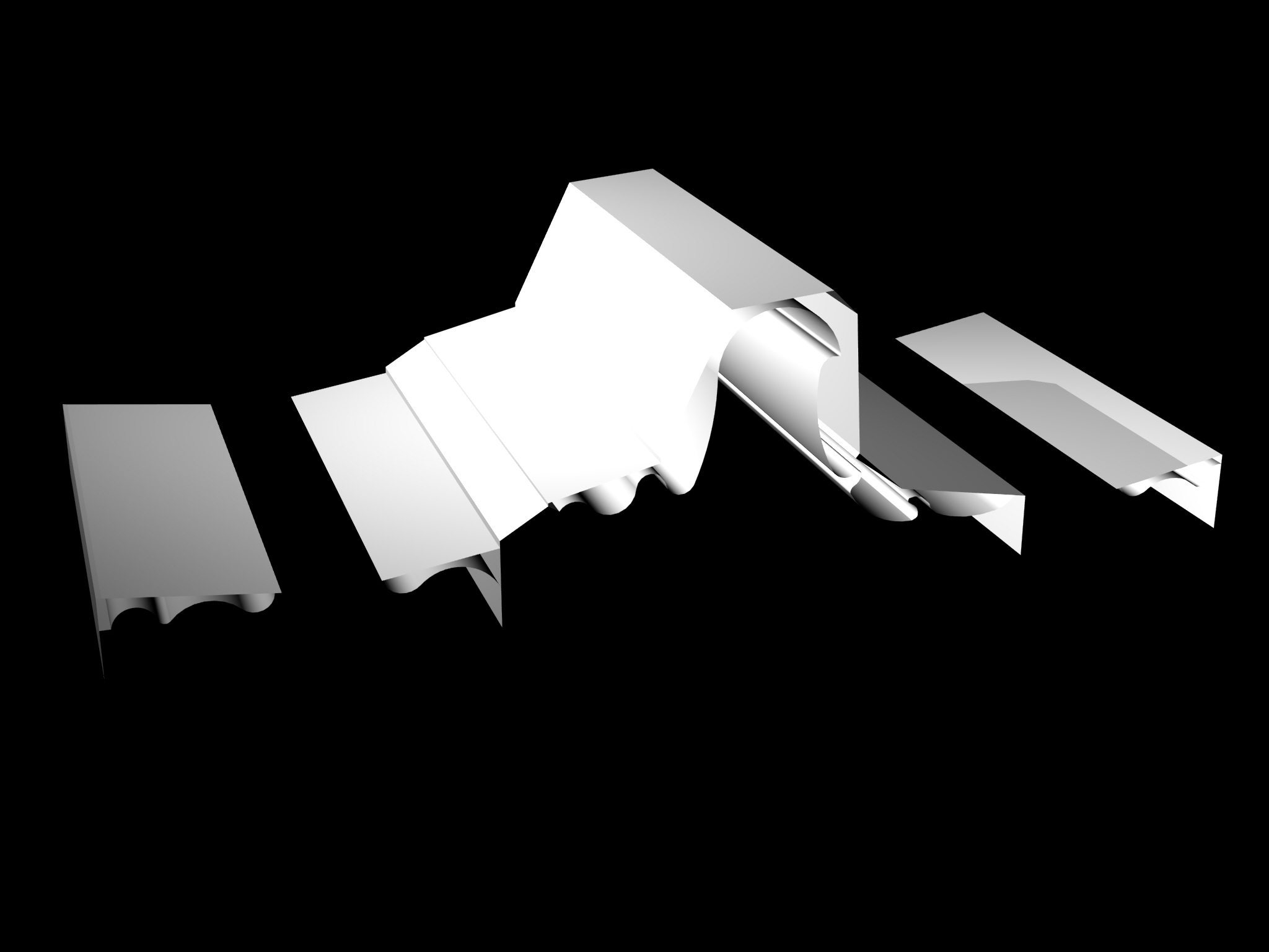
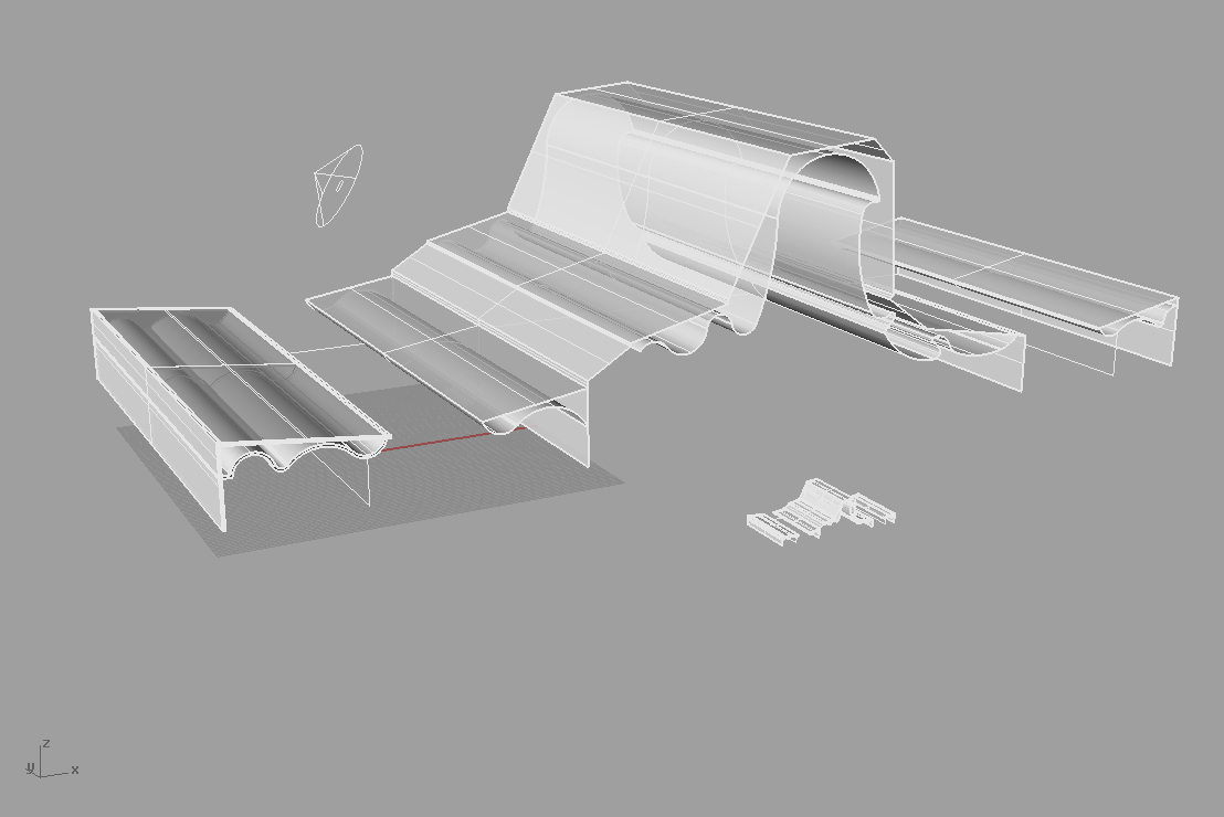
For Lesson 1 of the ANP494 course, the objective is to model the curvilinear ceiling surface of Utzon’s Bagsvaerd Church. The first step (Fig.1) is to import a 2D copy of the section and simply trace a series of circles which will ultimately form the ceiling (Fig.2). Fig. 3 illustrates the polyline after trimming the circles which form the ceiling. After joining the polylines, extrude the surface with the extrude command in a straight line command(Fig.4). Repeat the process for the remainder of the polylines (Fig.5). Fig.6 shows a close-up view of the ceiling surfaces. (**Note** I chose to ‘cap’ the surfaces but received an error message which stated that one or more of the surfaces were not joined and thus never figured out how to cap this complex form.) In Fig.7, I changed the layer color to a grey with the intent of rendering. A spotlight was added to achieve a shadowed effect in the rendering. Figs. 9 and 10 show the rendered surfaces. The former with edges rendered, the latter without.