Thematic Maps: Metropolitan Lima

Upon meeting with thesis co-chair, it was established that site selection needed justified. In McHargian fashion, the intersection and overlap of multiple systems reveals the approriate location of intervention and urban accupuncture.
Metropolitan Lima: Mass Transit Map
![]()
An aerial image indicating the existing mass transit routes in Metropolitan Lima, Peru. Shown in blue is the Metropolitano Bus Mass Transit, in yellow is the newly functioning Tren Electrico of Lima. For deciding which district to select for the thesis, the latter was chosen as a location indicator to maximize daily visibility by commuters in similar vein as the PREVI Project had done.
Ecological Urbanism + Informal Open Space

Berlin Studio: Pumpwerk Multifamily Housing


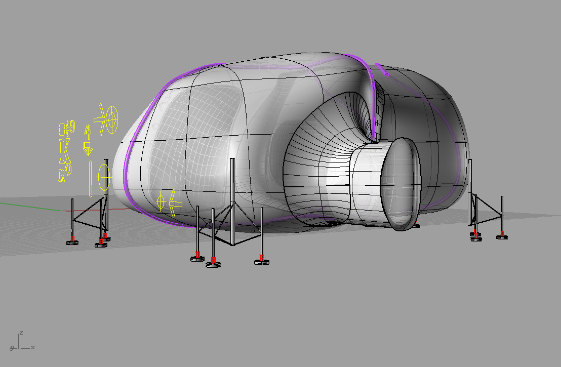
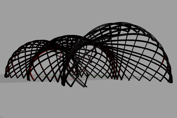
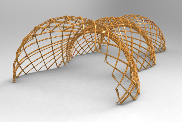
Rhino Lesson 7: David Greene Living-Pod Archigram Genius
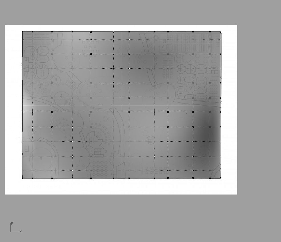
STEP 1. IMPORT IMAGE AND SCALE
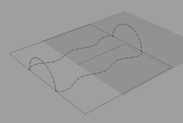
Double click on the left view to show full screen. Rick-click Left title box in blue, scroll to Background Bitmap > Place. With Ortho checked, draw a vertical polyline of 18’. Right-click Left title box in blue, scroll to Background Bitmap > Scale. Drag vertical line to side. Click Dimension Toolbar at top > Linear Dimension.
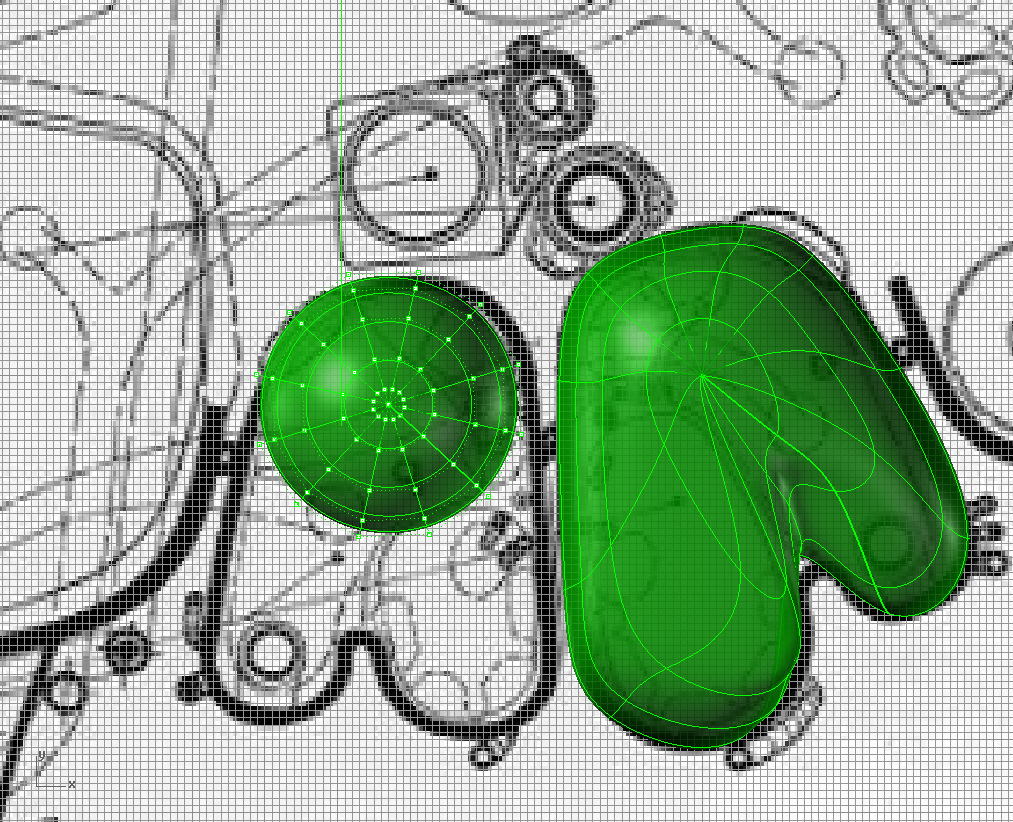
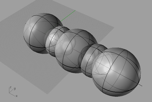
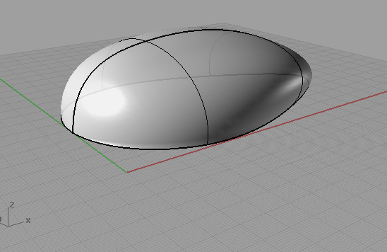
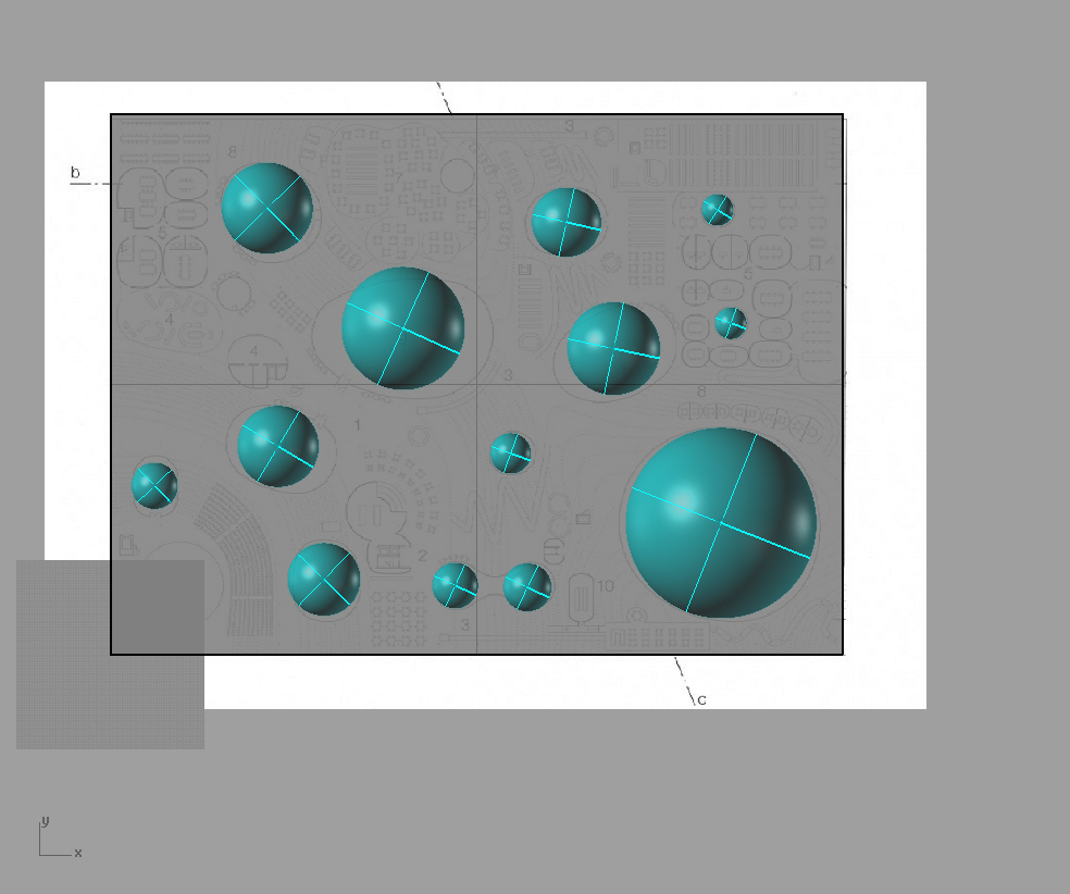
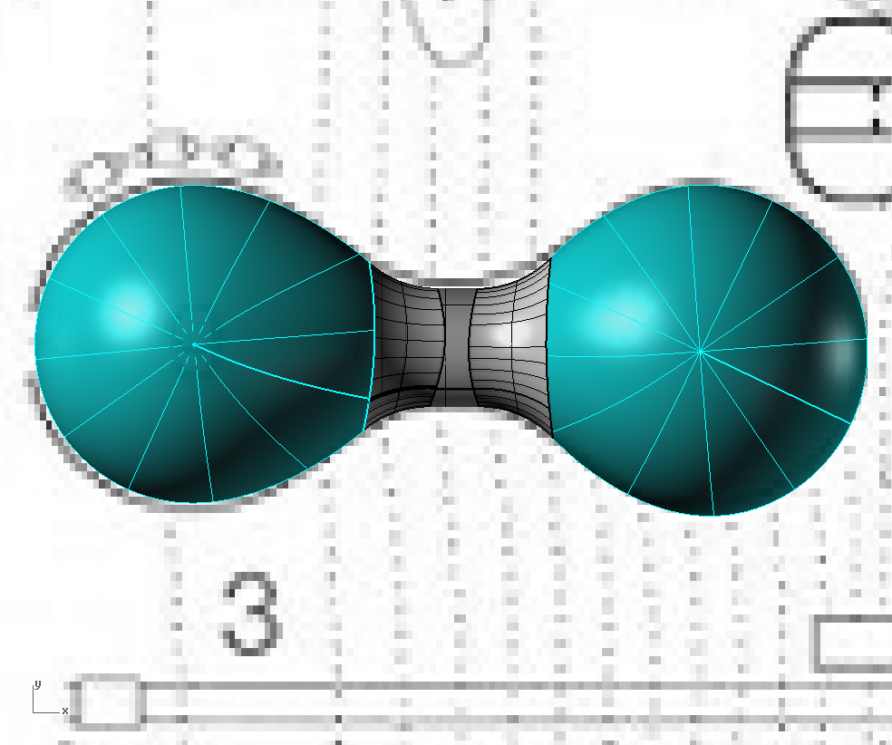
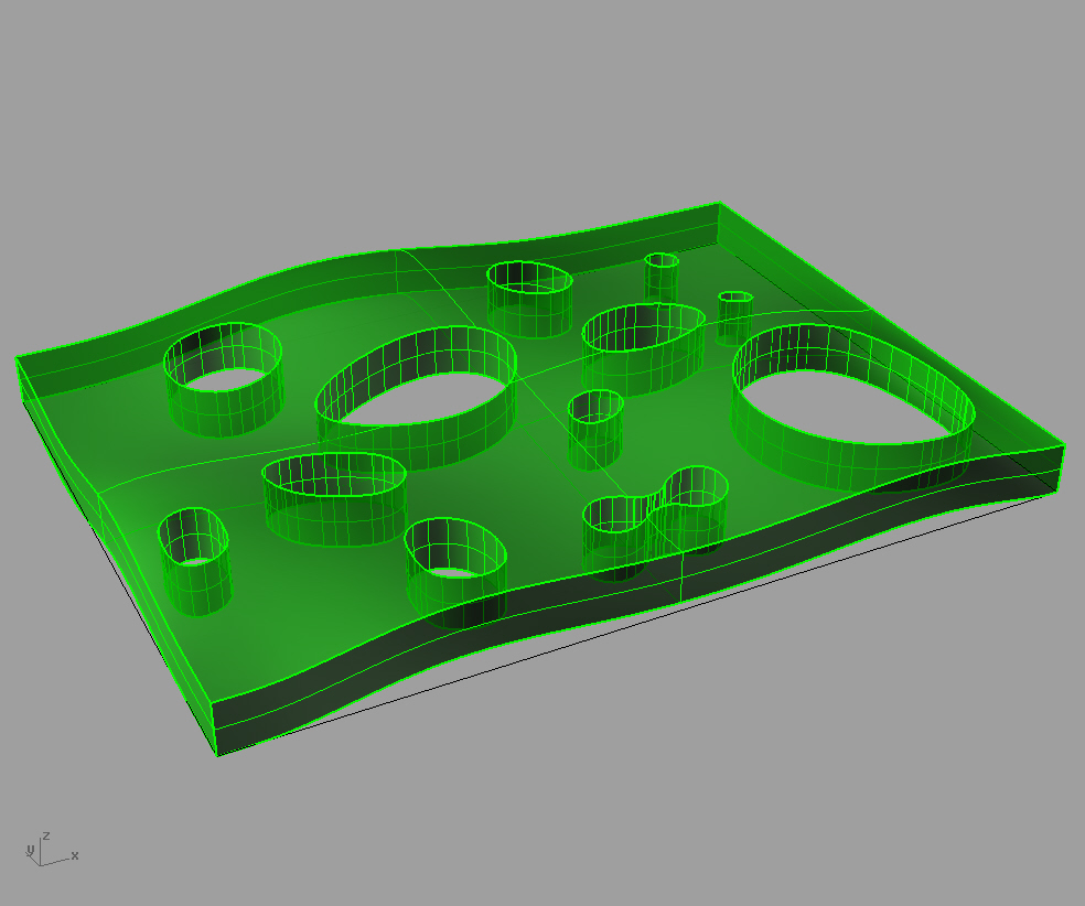
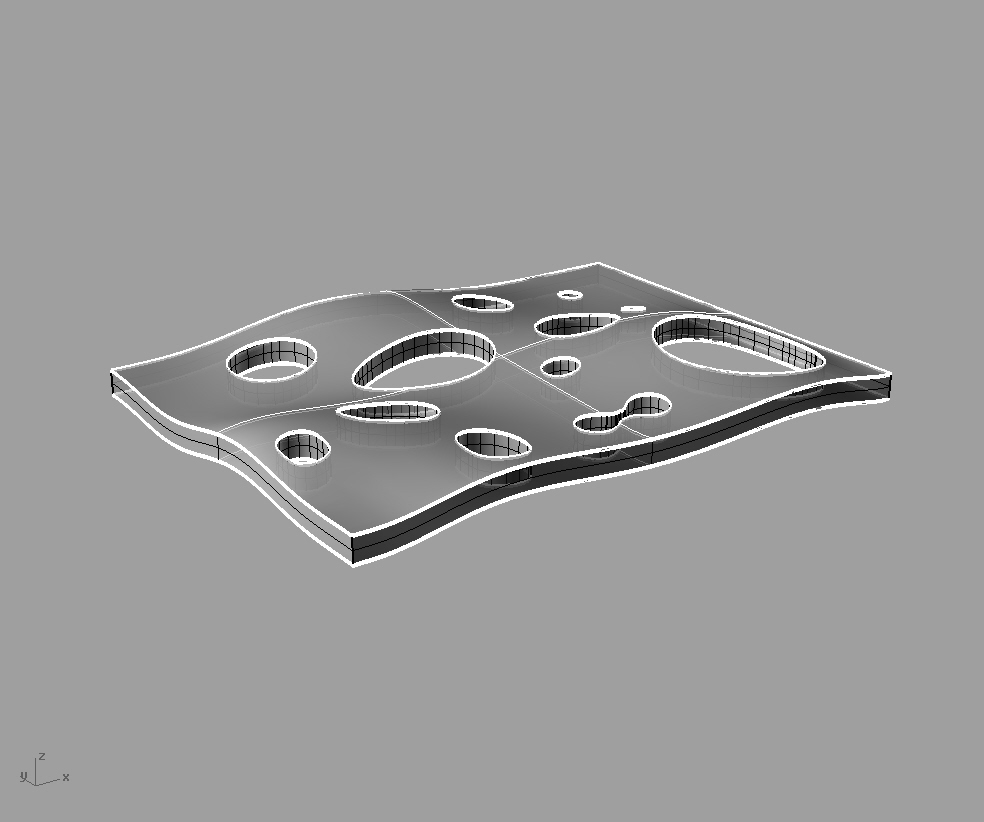
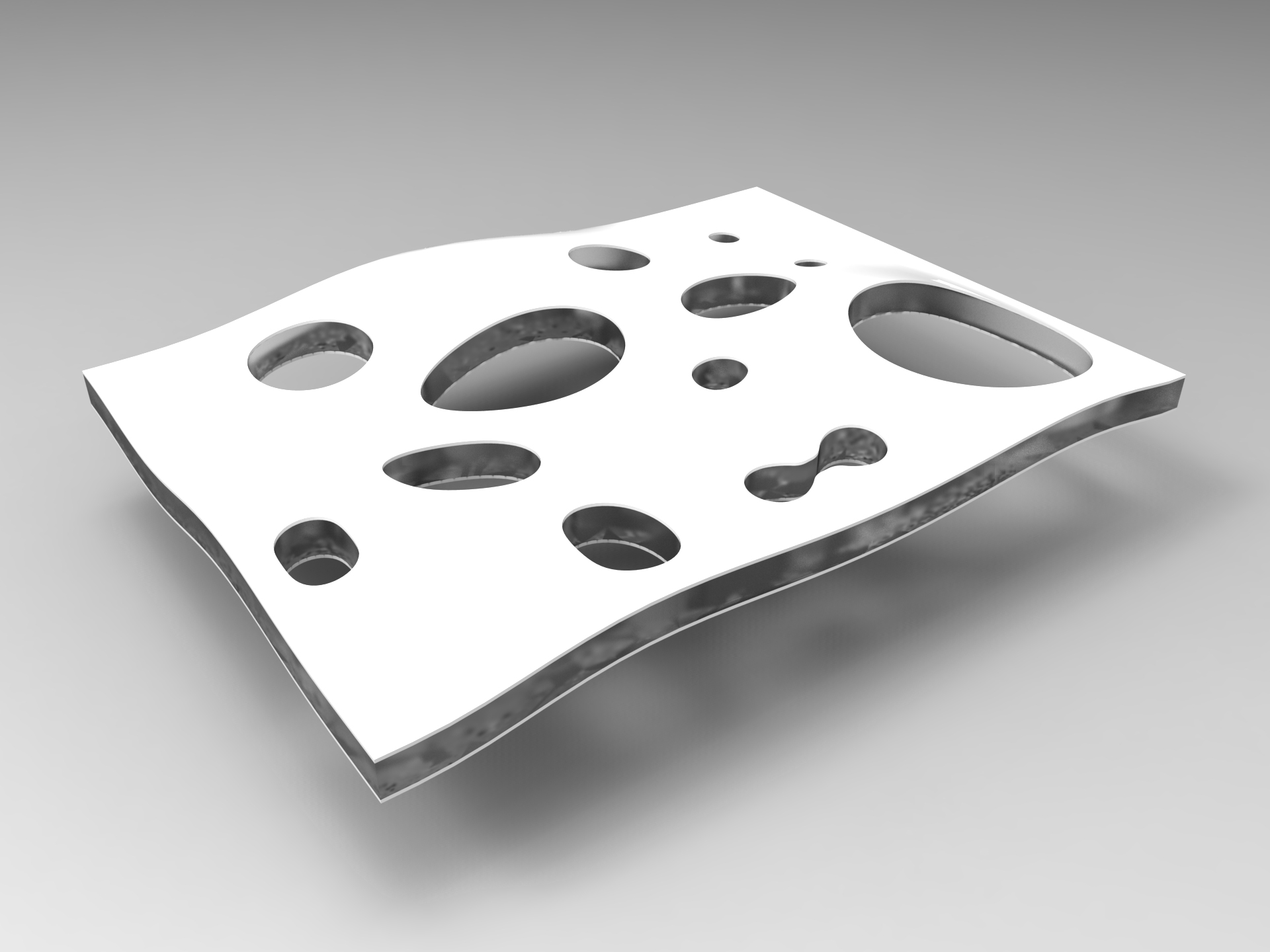
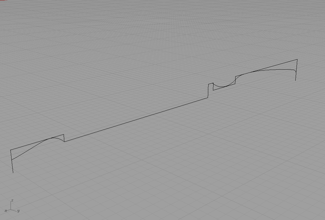
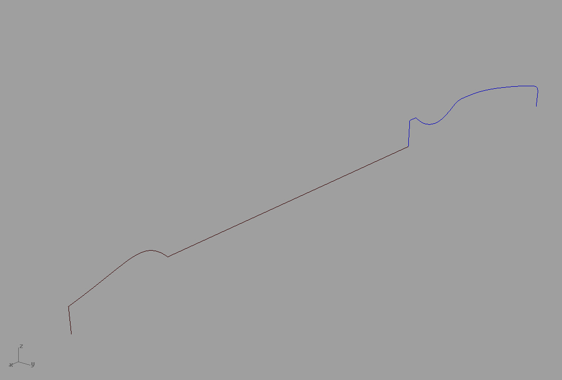
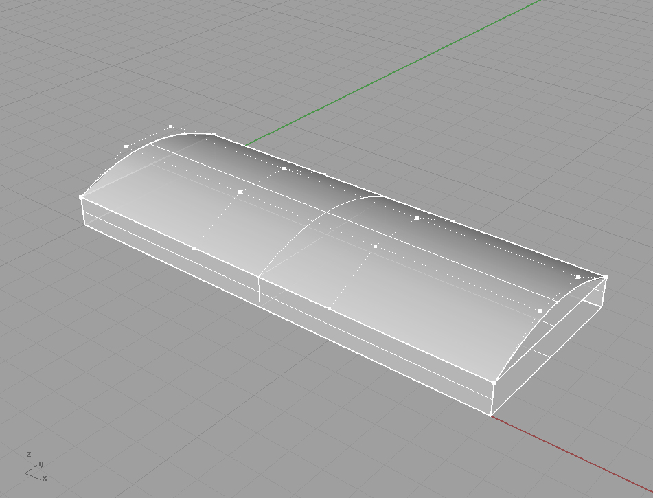
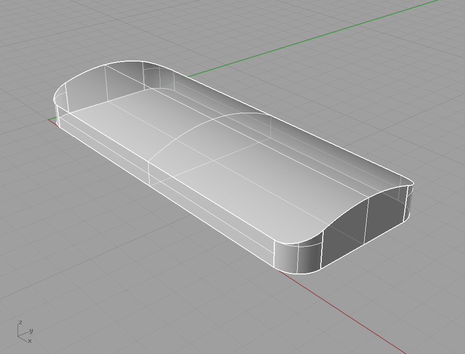
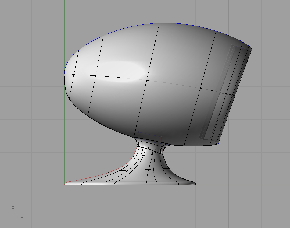
STEP 2. DRAW SPHERES FOR BODY MASSING
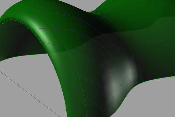
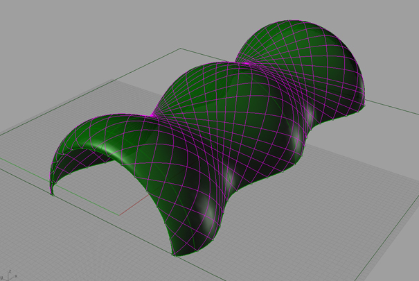
In plan, draw two spheres. Using all views, warp to shape by turning on control points. To get more control points, use rebuilt tool in command line. These basic masses will serve as the basic forms of the Living-pod. The process is the same for the smaller amorphous elements attached to the exterior. Use Boolean Union to combine warped spheres into a singular form once complete. Add this to a new layer.
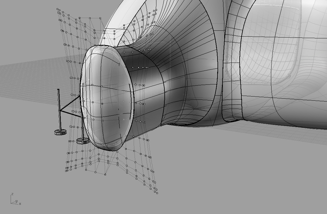
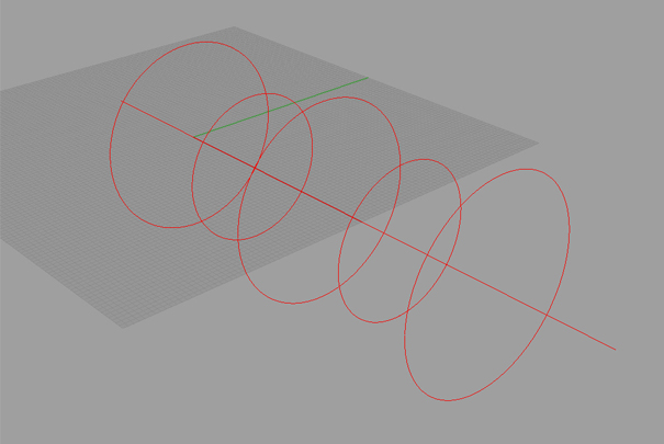
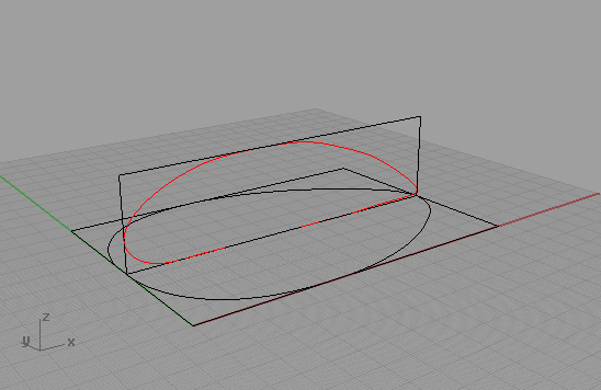
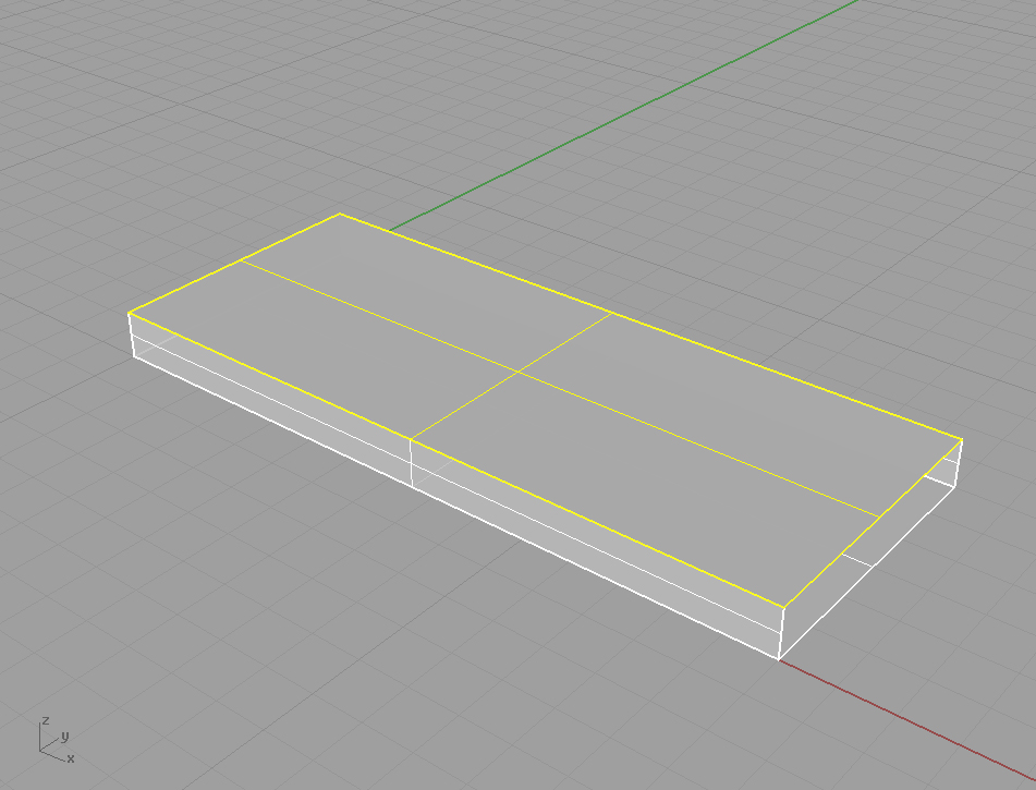
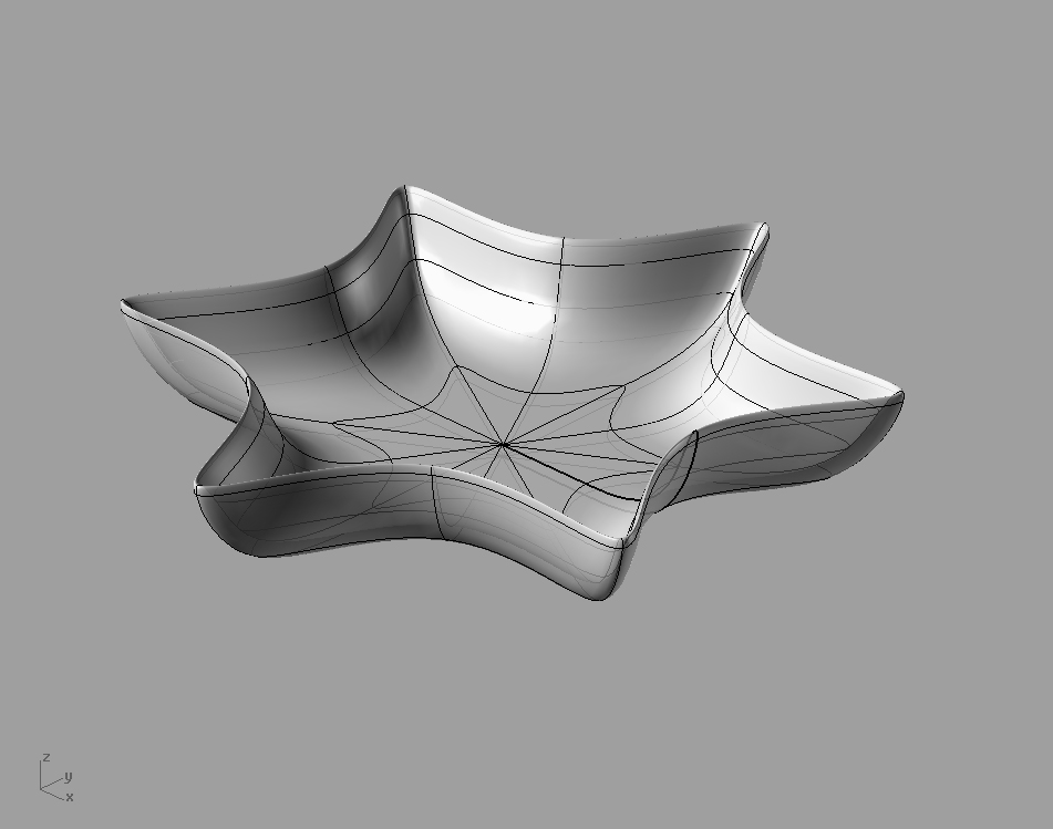
STEP 3. DRAW THE ENTRY.
Import a view of the entry. Scale bitmap as indicated above. Draw an ellipse. Curve >Ellipse > From Center. In Left View, Offset 10 feet. In Front View offset 3”. Loft curves to create surface and extrude. Use Trim Command to remove excess interior cylinder. Use Fillet to round the entry edge corners. FilletSrf > Radius=5.00.
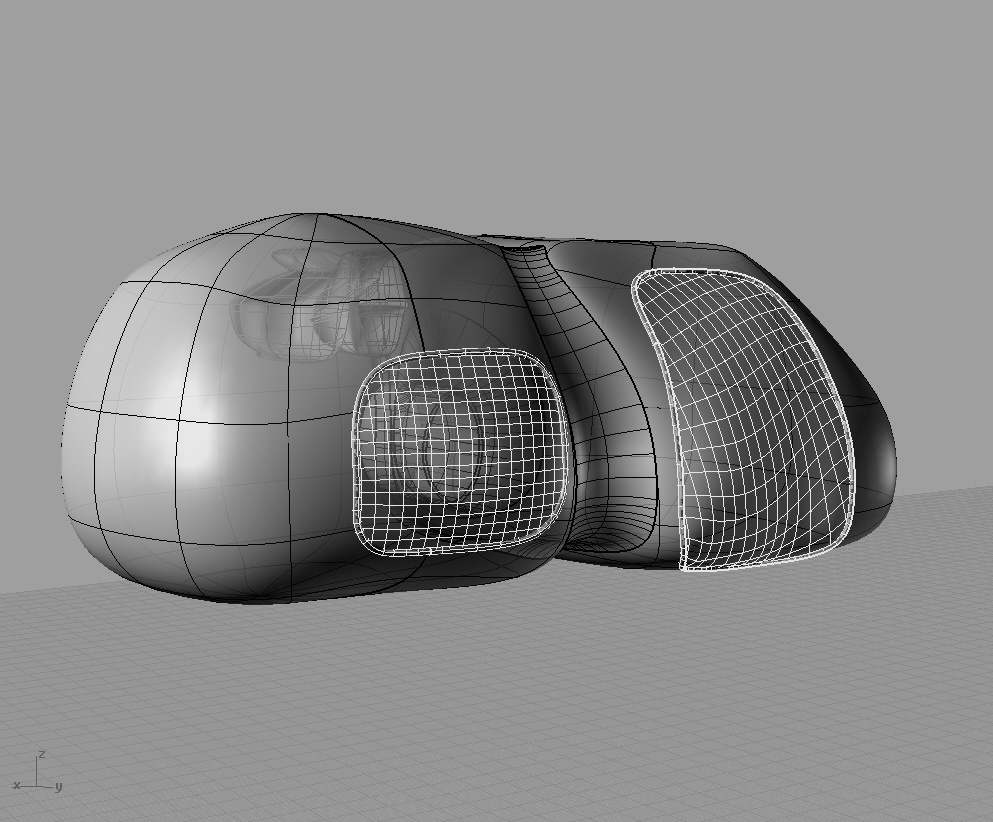
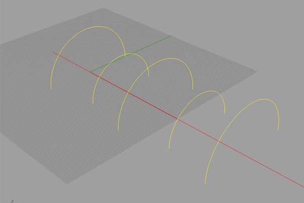
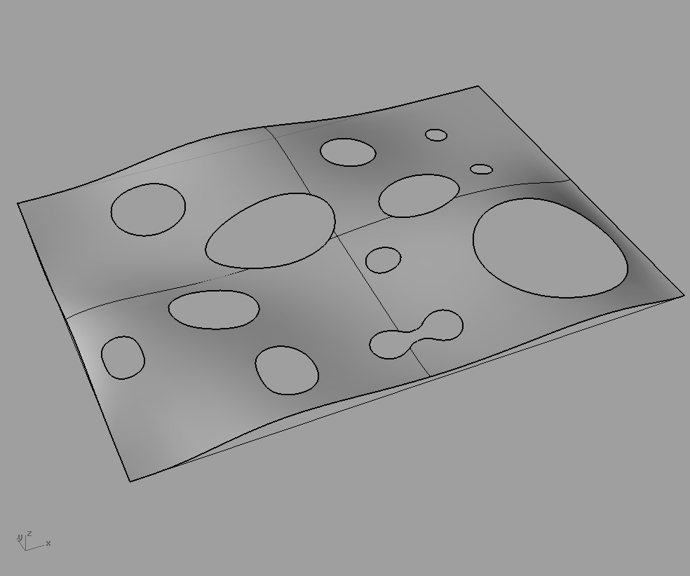
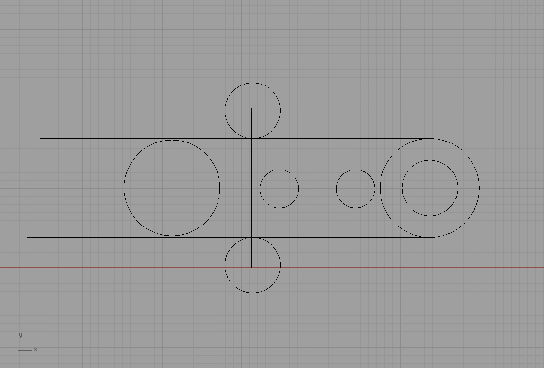
STEP 4. DRAW THE WINDOWS
In the Top View, trace the plan of windows. Offset curves up 2’ in an elevation
view of your choice. Once offset, move each curve accordingly to create the profile of the window before lofting the curves. This will create a more accurate profile. I have chosen to use the Left View to do this. To create more accurate mullion elements, rotate the offset curves normal to the surface. I did this manually, perhaps you may find a command which does the same operation. As you approach the tops and bottoms of the window openings, you may have to scale in 1 dimension while in the Front View to get the mullion elements to appear in correct locations.
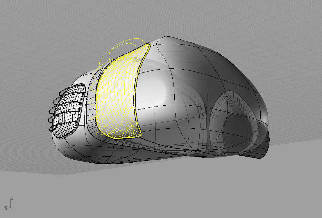
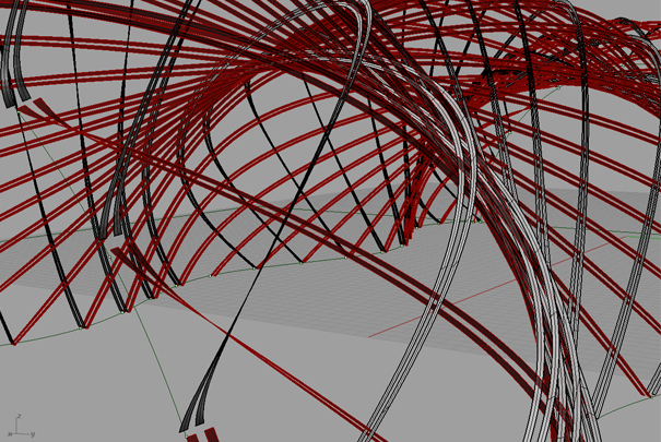
To cut the openings, trace an elevation view of Living-Pod. Offset the curves and loft. Trim the window openings and patch. Next, extract wireframe from the patched surface and pipe the curve. Pipe > Diameter = 4”.
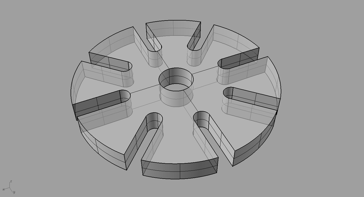
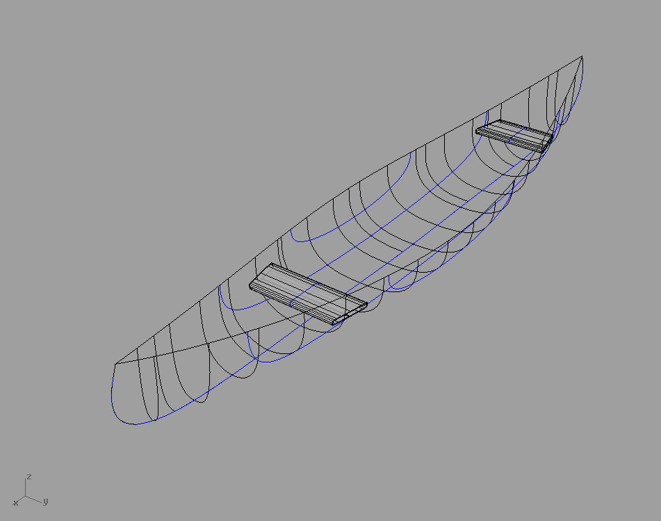
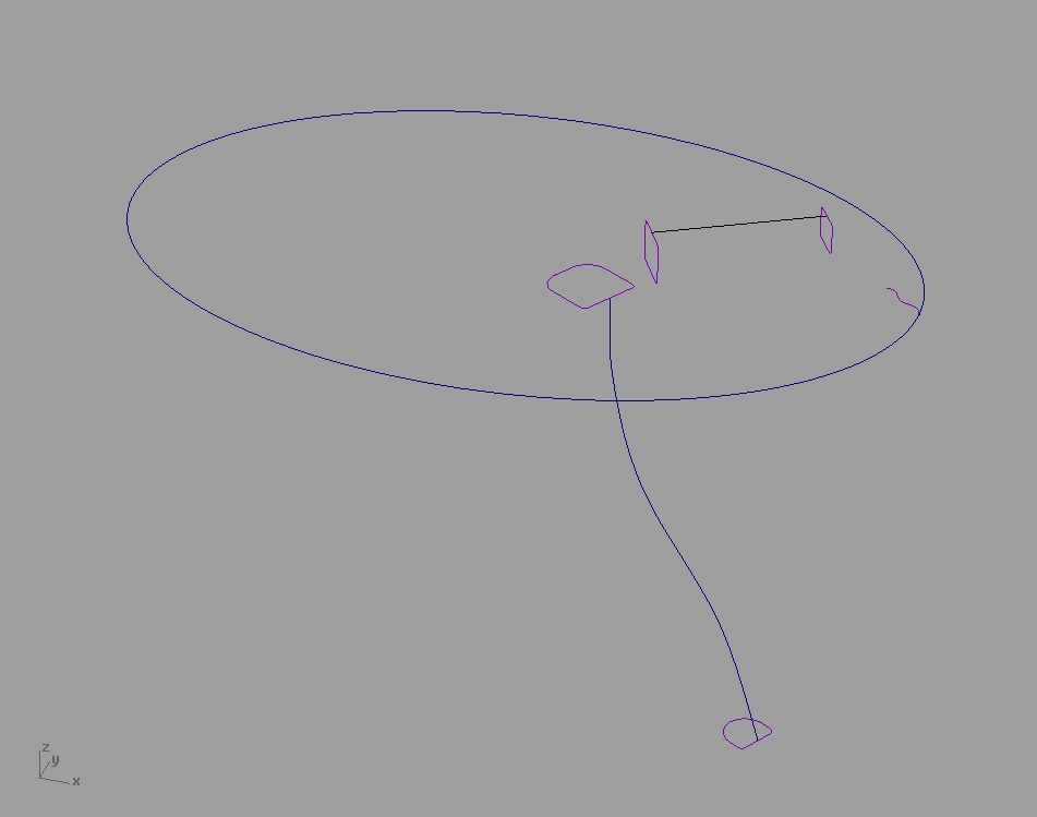
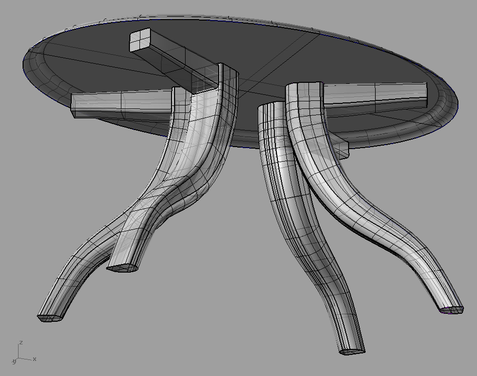
STEP 5: CREATE THE LEGS
In Plan, trace the circular footpads of the Living Pod legs. Extrude these elements and cap (ExtrudeCrv > Select Curves to Extrude > Extrusion distance = 3″ Cap = “yes”. Once two are drawn, mirror the image to get an accurate placement for the last two footpads. For the Remaining Four leg post foot pads, simply copy and paste elements, mirror and rotate accordingly while in the Top View. Draw the center posts for each landing pad. Extrude the central post 7′ and offset 2′ up. The foot pad posts are extruded 4.5′. Connect with diagonal lines for bracing as shown and pipe as illustrated above.
STEP 6: CREATE PIPES AND LOGOS
In plan view, draw polylines representing the airtube pipes. Select all, then in elevation view move all lines above the entire model using Ortho Mode. Use the Project Tool to project the image onto the exterior of the model. Select each polyline on the model and “pipe”. To create the logos, trace the images in elevation view and project onto the side of the Model. If Project command does not work, use the Pull command.